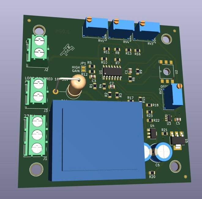
This is a board that converts the pressure in a pipe created by the level of a liquid above the pipe’s entrance, linearly, to a voltage of 0 to 10 volts and simultaneously a loop current in the range of 4 to 20 mA.
It can be used with small effort as a meter, or together with a PLC or other board, as a controller or alarm or whatever comes to your mind. It has a sensor that can handle pressures up to 4 meters of water or 5.8psi. Other types can be used if you try.
I release it as open source hardware, without any claims or guaranties. Use your mind and be safe.
Be warned that the sensor used, is bare die, is not protected by an insulating film like more expensive sensors. That means that you have to make sure no water vapour or other corrosive substance will reach the sensor.
I designed it with LCSC availability in mind, but this was a few months back. The current availability might have a completely different picture. The PCBs and assembly were made by JLCPCB, very quickly as always. I still have a few boards, SMD populated (with sensor and trimmer pots) available for anyone interested.
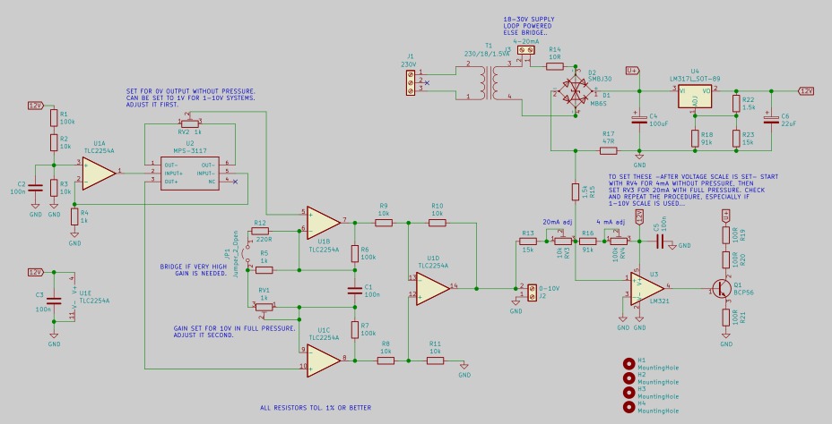
See below the schematic:

You can find a PDF version in better dpi in the zip files below.
Here, in the zip files, there are the gerber files if you just want to make the PCB and the KiCad project if you want full editing capabilities.
A small demonstration can be seen here:
You have to do a little screw turning, to adjust the multi-turn potentiometers to fit your application. Use the comments in the schematic as a guide. You must null the offset first, adjust gain for your max level and then adjust the current loop accordingly.
You can power the device by 230V through the transformer, or by the loop power supply. In the latter case if you don’t want to mount the transformer, you should put a wire where the secondary should be (pins 3 & 4 of T1) to keep the loop… well, a loop!
I hope you find it useful,
Have Fun!


