
In a previous post, I tackled the conversion of a CAD program (KiCad) output position file, to the pick and place machine’s (NeoDen 4) needs.
The script I provided there did a great job in formatting the .CSV output file according to Neoden input requirements, and converting the component coordinates from the kicad reference to the p’n’p machine’s work space coordinates reference. The scale was not an issue, both are in millimeters, so it was only a matter of offset in both axles x and y.
All would work fine as long as the PCB would be affixed on the machine exactly as in the CAD program, its sides completely parallel with the machine’s x and y coordinate system. Since this is not easy, there was a need for some manual fiddling to correct the positions of each component in the machine’s software. This was done much easier through this script as the provided positions were very close to the actual and one could recognize very easily each component and perform the correction fast.
This was not so good though, and since Neoden’s software recognizes the angle the PCB differs from perfect alignment, and gives this number, I decided to make some enhancements to the script.
In the image below you can see a PCB placed in some random angle (red rectangle). The black rectangle shows where the angle-uncompensated KiCad position would be.
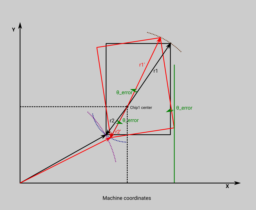
Theta_error is the angle the PCB orientation differs from the expected. I will spare you (and me) the math, it is obvious from just looking at the image that the same angle error is applicable to all the points in the PCB’s area, if your vectors are referenced on the PCB itself. In addition the length of vector r1 is equal to the length of vector r1′, the same with r2 and r2′. In contrast, the lengths of the vectors referenced to the machine coordinate system do not have the same length.
The above shows clearly the course of action I took. I converted all Cartesian coordinates to polar, referenced on the already needed Chip_1 position as the zero point. I kept all r coordinates as were, and applied the theta_error given by the machine (and manually given as an input to the script) to all theta coordinates. Then I converted back to Cartesian all coordinates, referenced to machine’s zero point.
Not so hard after all, I should have done it sooner, not waiting for a board with many components to remind me the work involved in manually correcting all the positions!
I usually export the positions for a single board from KiCad, and then use the Neoden’s software to create the panel. You can try if you wish to export all the panel but I don’t recommend it. You still have to manually check rotations, KiCad libraries don’t always agree with the actual rotation on the machine! Anyway the software on the machine does a good job paneling, even does boards with 180 degrees rotation in the same panel, as many of mine are. Still this script saves me a lot of work, I am pleased!
The new script is on the following link:
https://drive.google.com/file/d/1uaIgWoXoJV1Y0pTPP80v1X_5H6G4rwG0/view?usp=sharing
Use it as you see fit, no guaranties whatsoever but always have fun!
P.S. KiCad in version 6 didn’t change the position file format, so the script works just fine!
Update: the script is modified as per comments below!
5 thoughts on “KiCad to NeoDen part 2”
Hi question about the python script for kicad i cant get it to work, used different versions of python, i renamed the script after trying a couple times, tried both versions both do the same. thx alot
We will offset positions according position of Chip_1 on Neoden… and compensate for the angle error of PCB placement!
Give Chip_1 X position: 12
Give Chip_1 Y position: 36
Give PCB angle: 0
Parsing r10003.0-all.pos
Calculating Offset
X_offset: 18.482 — Y_offset: -27.453
Traceback (most recent call last):
File “kicad2.py”, line 116, in
main()
File “kicad2.py”, line 98, in main
xi_ndn, yi_ndn = theta_error(float(line[3])+offsetxi, float(line[4])+offsetyi)
ValueError: could not convert string to float: top
This was because Maxi had empty value fields in the libraries in use.
Since it is not easy to address all possibilities of missing data, I updated the script to just complain about it, give the data line number (counting from 1 so you can find it on your text editor) and exit.
Have fun,
Theodore
Hello! I found a bug in the angle adjustment code, lines 48 through 60. I have implemented a quick fix that seems to work. Basically, you’re checking if both X and Y are nonzero, but if either of them is zero it’ll set both to zero. In panels with multiple boards, for instance this means every component that is vertically or horizontally aligned with the first component gets placed on top of the first component. The if/else check seems to be intended to prevent division by zero, but by checking yi as well and by using a default value, it causes major problems in panels.
The fix I implemented is to get rid of lines 58-60, unindent 49-57, and replace line 48 with these two lines:
if xi == 0:
xi = 0.00000000001
By the way, I have a Neoden 3 TM245P, and the script totally saved me. Thanks so much for having it online!
Hey, thank you very much!
The idea for that IF check was to keep first chip un-altered. I thought division by zero was taken care as a by-product. (It was not!)
I had not thought this through.
I will update the script as you suggest, it seems fine. I will be working with the machine sometime next month, so I’ll check it then.
Thank you again for getting in touch to share your solution. It is my pleasure to find out that something I did was useful to somebody.
Regards,
Theodore